Motivation
Our previous work developed a cockroach-inspired robot capable of leg-assisted, winged self-righting, and a robot simulation study revealed that the outcome of this strategy depends sensitively on wing-leg coordination. Here, we further elucidate why this is the case by developing a template to model the complex hybrid dynamics resulting from discontinuous contact and actuation.
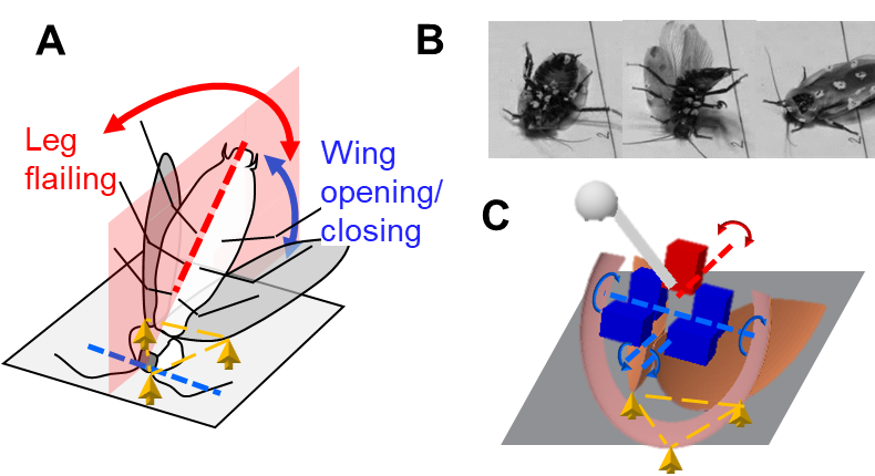
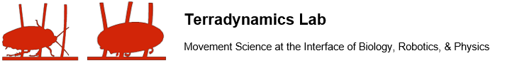
Fig. 1. Leg-assisted, winged self-righting on the ground and previous observations. (A) Schematic of strategy in a discoid cockroach. Yellow arrows and triangle show metastable triangular base of support formed by head and two wings in contact with ground. (B) Snapshots of a cockroach self-righting. (C) Simulation robot with a head, two wings and a pendulum leg.
Previous work
In recent studies, we developed a cockroach-inspired self-righting robot and a multi-body dynamics simulation robot. The wings and leg are controlled by motors to oscillate with simple actuation profiles.
For every wing opening attempt (every cycle of wing oscillation), wing-leg coordination can be measured by the phase φ between wing and leg oscillations (defined in Fig. 2A caption). We varied phase to test whether the robot self-righted. Unless leg oscillation amplitude was very small or very large, for given leg oscillation amplitude, self-righting was always more successful at some phases (e.g., φ = 0%, 50%, and 100%) than others (e.g., φ = 25% and 80%).
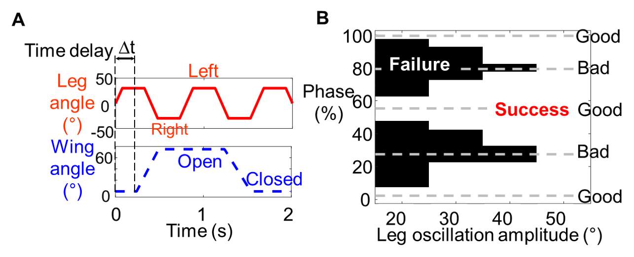
Fig. 2 Actuation in simulation experiments and the influence of phase on self-righting. (A) Actuation profiles of wing and leg oscillations. Wing-leg coordination is measured by phase φ = ∆t/Tleg, where ∆t is time delay of start of wing opening from start of the first leg oscillation, and Tleg is leg oscillation period. Wing opening amplitude is the maximal wing opening angle. Leg oscillation amplitude is the maximal leg angle (absolute value) to either side from middle. Leg starts from the middle (leg angle = 0) at time t = 0. (B) Self-righting outcome (white: success, black: failure) as a function of phase and leg oscillation amplitude at a given wing opening amplitude (76°), from simulation experiments in previous study.
Template model design
To understand the mechanism of how the phase between wing and leg actuation affects self-righting outcome, we developed a template of leg-assisted, winged self-righting. For simplicity, our template only models planar dynamics in the transverse plane (Fig. 3), considering that leg-assisted, winged self-righting eventually succeeds by body rolling.
Our template has six simplifying approximations:
(1) The body is a point mass M, and the leg mass m is concentrated at its tip.
(2) The wings and leg linkage are massless links only for support and connection.
(3) Wing-ground contact is a point contact. It slides during wing opening but stays fixed when the body rotates around it.
(4) The wings and leg linkage are straight and rigid.
(5) Wing-ground collision is instantaneous and inelastic.
(6) Wing and leg motors start and stop instantaneously.
Fig. 3. Template. (A) Schematic of template. Two point masses represent body (orange, B, mass M = 210 g) and leg pendulum mass (red, L, m = 50 g). Three massless links represent wings (blue segments, R = 12 cm) and leg linkage (red segment, r = 7 cm). θW and θL are wing and leg angles. Increasing and decreasing θW correspond with wing opening and closing, respectively. (B) Actuation profiles of template. Angular velocities of wings (blue) and leg (red) as a function of time.
Dynamics
The template is a hybrid dynamical system because of discontinuity in wing and leg velocities (instantaneous actuation states) and hybrid contact between the wings and ground. For continuous motions, we used forces to solve for dynamics. For instantaneous events, we used impulse to solve for the change of velocity via conservation of angular momentum. Below, we describe how we solve the dynamics for six representative cases (Fig. 4), organized into continuous motions (Fig. 4A) and instantaneous events (Fig. 4B).
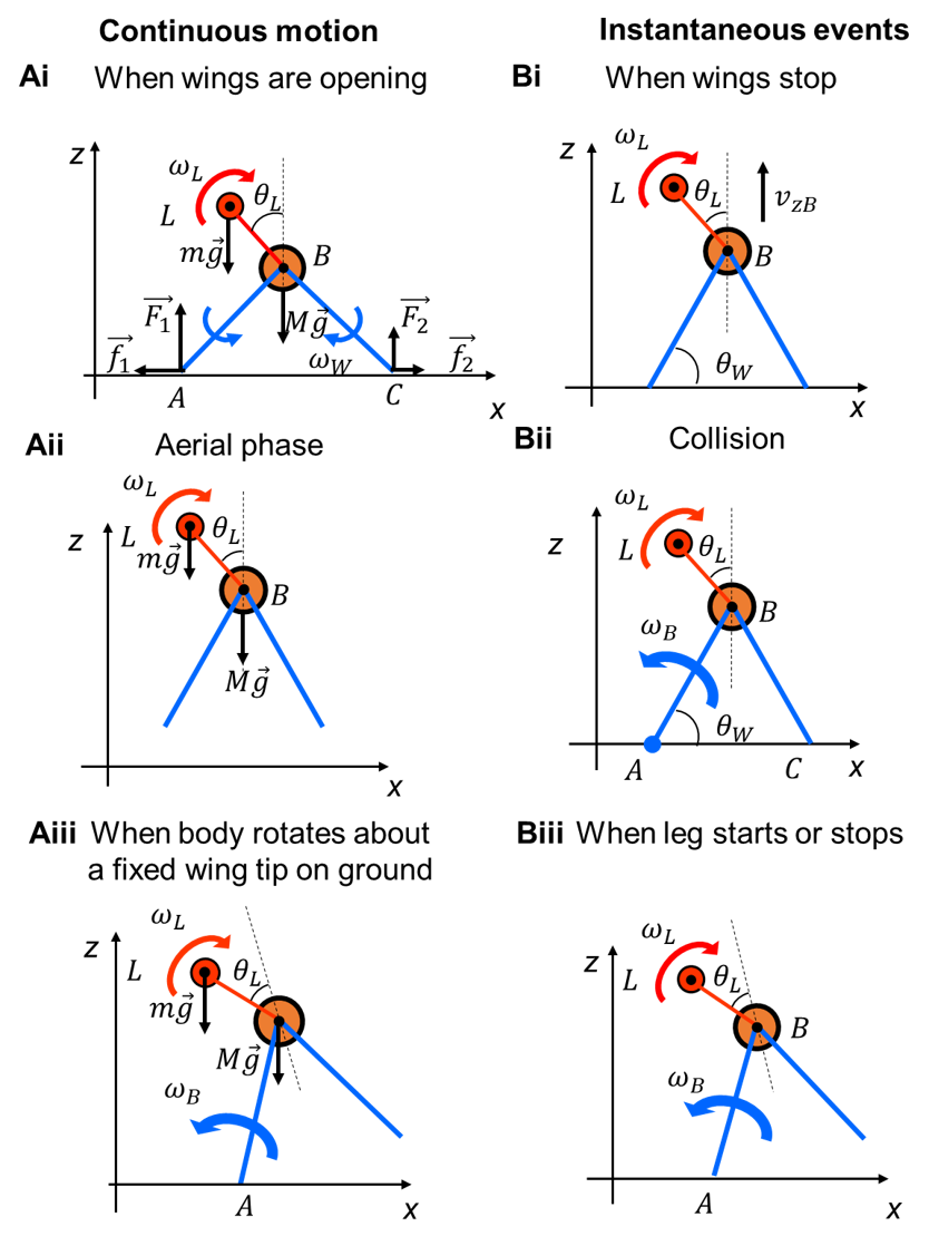
Fig. 4. Hybrid dynamics. We show six representative cases with different actuation and contact states, with definitions of forces (F1, F2, f1, f2, mg, Mg), wing tips (point A, C), and angular velocity (ωL, ωB ). (Ai-iii) Continuous motions. (Bi-iii) Instantaneous events.
Mechanical energy barrier
First, we calculated the potential energy barrier of the template. Consider two snapshots during self-righting (Fig. 5A), with CoM at a local minimum (left) and a local maximum (right). A potential energy barrier is the increase in gravitational potential energy from the local minimum to maximum, Ebarrier = (M + m)gΔh.
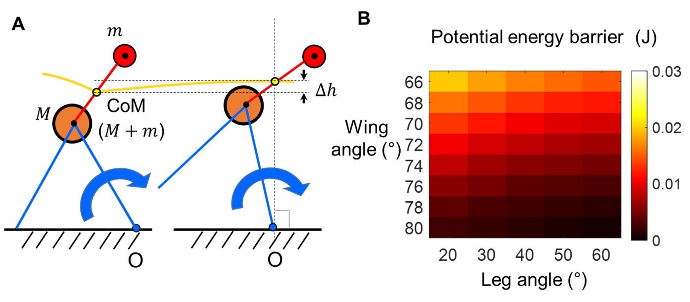
Fig. 5. Potential energy barrier. (A) Two snapshots of template rotating about a fixed wing tip O. Yellow curve is CoM trajectory. ∆h is CoM height increase between snapshots. (B) Potential energy barrier from template as a function of wing and leg angles.
Mechanical energy budget
The robot and the discoid cockroach often struggled for multiple attempts before they could self-right. Although the motors/muscles do positive work when the robot or animal opens the wings and flails the leg(s) (Fig. 1A, C), the mechanical energy injected may not be sufficient to overcome the potential energy barrier.
For the robot, this is because mechanical energy is dissipated at collision and motor stopping. To understand how wing-leg coordination affects self-righting outcome, we used the template to calculate how mechanical energy is accumulated from energy injection minus energy dissipation, and we compared cumulative mechanical energy with the potential energy barrier to assess whether self-righting is successful or not.
We used the template to calculate mechanical energy evolution of the system over the potential energy landscape. Both wing opening and leg stroke do work to change mechanical energy. Collision with ground dissipates energy.
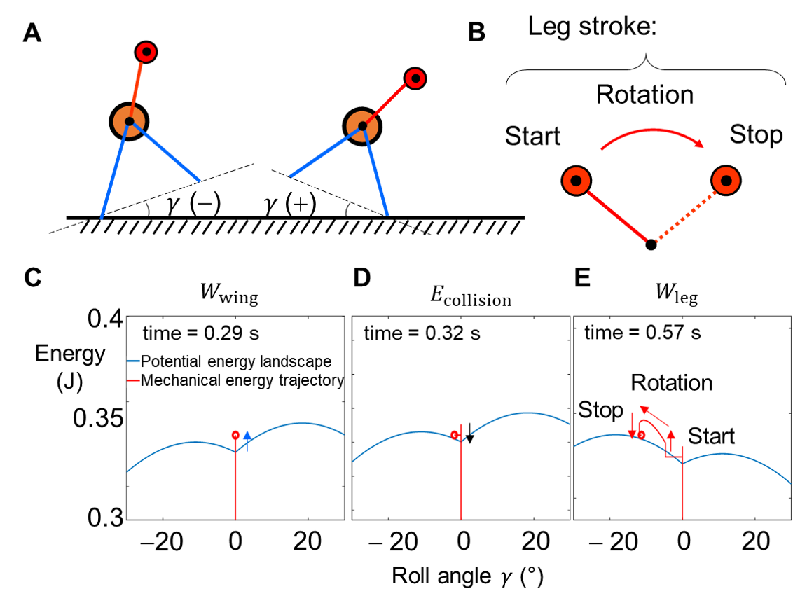
Fig. 6. Mechanical energy evolution of system from template. (A) Definition of roll angle. +/– is clockwise/counterclockwise rolling. (B) Definition of a leg stroke. Stroke direction can be reversed. (C-E) Example snapshots of system mechanical energy (red dot) evolution (red trajectory) over changing potential energy landscape over body roll (blue curve). C: When wing opening stops. D: When one wing collides with ground. E. When leg stops. Red curve is trajectory of system state from the beginning (t = 0 s).
To understand how phase affects system mechanical energy, we calculated contributions to cumulative mechanical energy from wings, leg stroke, and collision (Fig. 7, Wwing, Wleg, and Ecollision) for good and bad phases over a broad range of wing opening and leg oscillation amplitudes. We defined cumulative mechanical energy at the end of the first leg stroke as: Ecum =Wwing + Wleg – Ecollision
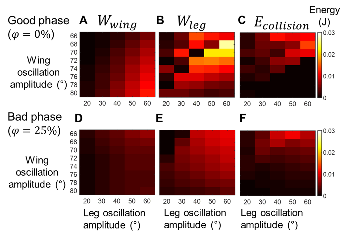
Fig. 7. Mechanical energy contributions for example good (top) and bad (bottom) phases. (A, D) Wing work Wwing(see definition in text), (B, E) work done by the first leg stroke Wleg, and (C, F) energy dissipation at collision Ecollisoin (absolute value), all as a function of wing opening and leg oscillation amplitudes.
Both Wwing and Wleg consist contributions from instantaneous events and continuous motions, whereas Ecollisoin is only from instantaneous events. Then, we evaluated mechanical energy budget, Ecum – Ebarrier, to understand why good phases lead to more successful self-righting than bad phases.
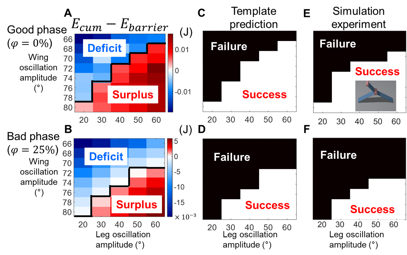
Fig. 8. Mechanical energy budget from template predicts self-righting outcome. (A, B) Mechanical energy budget from template—cumulative mechanical energy minus potential energy barrier. (C, D) Self-right outcome predicted by energy budget from template. (E, F) Self-righting outcome of a “2-D” simulation robot (inset in E). Data are shown as a function of wing opening and leg oscillation amplitudes for good (top) and bad (bottom) phases.
For both good and bad phases, the system has an increasing mechanical energy deficit as wing opening and leg oscillation amplitudes decrease, and it has an increasing surplus as they increase (Fig. 8A, B). Where the template transitions from having an energy surplus to a deficit (Fig. 8A, B, black curve) predicts where it transitions from success to failure (Fig. 8C, D). Clearly, good phases lead to greater mechanical energy surplus and smaller deficit than bad phases over the entire parameter space (Fig. 8A vs. 8B), resulting in successful self-righting over a larger range of wing opening and leg oscillation amplitudes (Fig. 8C vs. 8D). Considering that our previous observations were made in a different, 3-D robot, to further validate the template, we developed a “2-D” multi-body dynamics simulation robot using Chrono (inset in E). By performing simulation experiments over the same range of parameter space, we found that where the “2-D” robot transitioned from success to failure (Fig. 8E, F) well matched that predicted from mechanical energy budget from the template (Fig. 8A, B), for both good and bad phases.
Template predicted control
Because the template describes system dynamics fully and was validated against simulation experiments, we can use it for predictive robot control. To demonstrate this, we used the template to predict a new control strategy to further increase self-righting performance.
Our calculation revealed that, when a wing collides with the ground (Fig. 9A), leg torque drops instantaneously. Thus, our control strategy maximized Wleg by maximally delaying collision during leg stroke, or avoiding collision altogether.
We used the template to test our control strategy. Indeed, self-righting performance was further improved (Fig. 9D) beyond achievable by using good phase alone (Fig. 9C).
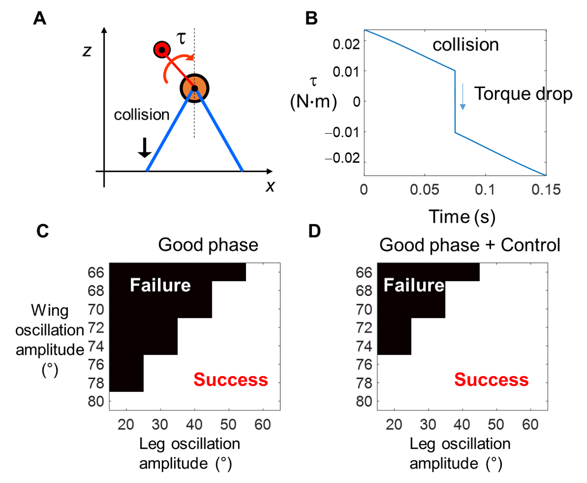
Fig. 9. Template-predicted control. (A) A collision with ground occurs during a leg stroke. τ is leg motor torque. (B) Leg motor torque τ as a function of time during a leg stroke. Torque drops at collision. (C, D) Self-righting outcome predicted from template with (C) and without (D) control using a good phase (φ = 50%), both as a function of wing opening and leg oscillation amplitudes.
Summary
We developed a template of leg-assisted, winged ground self-righting and used it to elucidate why wing-leg coordination affected self-righting outcome. With good coordination, the system better accumulates mechanical energy to overcome the potential energy barrier and thus self-rights more successfully. Besides providing mechanistic understanding of this complex hybrid dynamical system, we demonstrated practical usefulness of the template by predicting a new control strategy that further improves self-righting performance.
Related publications
- Xuan Q, *Li C (2020). Randomness in appendage coordination facilitates strenuous ground self-righting, Bioinspiration & Biomimetics, 15 (6), 65004 PDF (Movies 1 2 3)
- Xuan Q, *Li C (2020). Coordinated appendages help accumulate energy to self-right on the ground, IEEE Robotics and Automation Letters, 5 (4), 6137-6144 (also appearing in IROS 2020) PDF Video IROS pre